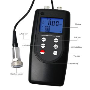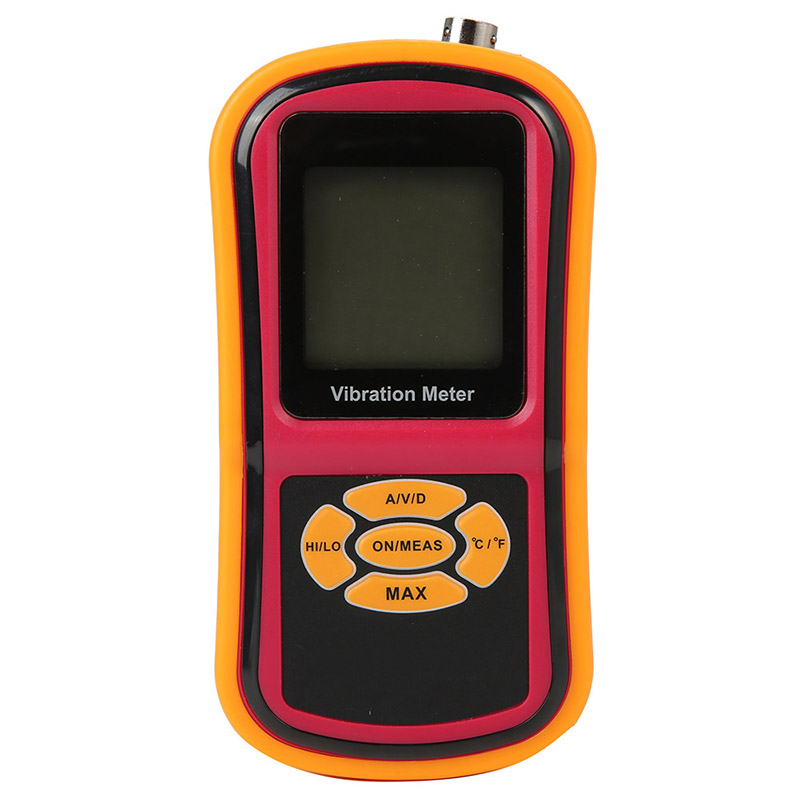


3-channel vibration meter accelerometer piezoelectric transducer
Features:
- Uses piezoelectric acceleration transducer to convert vibration signal
- 3 same parameters in one display for 3 position measurement or 1 position measurement specified, showing 3 different parameters of velocity, acceleration and displacement in 1 display.
- Wide Frequency range ( 10Hz~10kHz) in acceleration mode
- Designed for easy on-site vibration measurement of all rotating machinery for quality control, commissioning, and predictive maintenance purposes
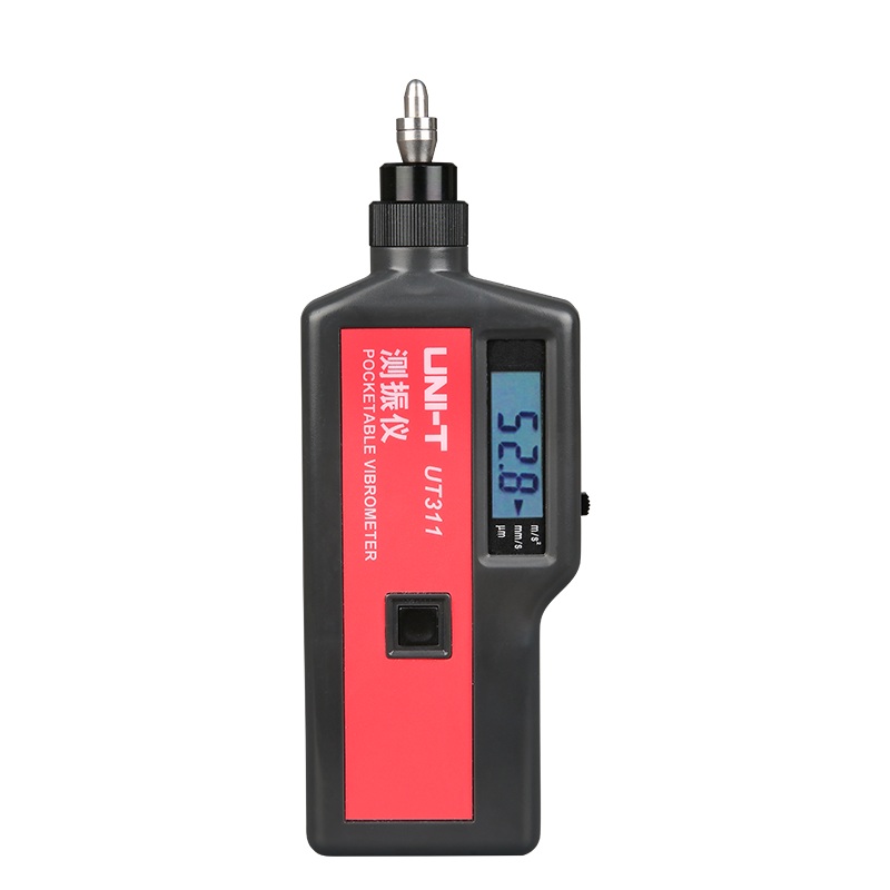
- LCD digital display with backlight
- Lightweight and easy to use
- High-Quality accelerometer for accurate and repeatable measurements
- 3 accelerators for 3-channel vibration measurement
- Bearing condition monitoring function
- Manul or Automatic power shut off to conserve power
- With MAX value HOLD function
- With low battery indication
- AC output socket for headphones and recording
- In accordance with ISO 2954, GB13823.3, used for periodic measurements, to detect out-of-balance, misalignment and other mechanical faults in rotating machines
- USB data output to connect with PC (Cable & Software is not included in the set)
- Bluetooth data output choice (adapter and software is not included in the set)
Specification
Sensor: 3 Piezoelectric Transducer
Measuring Range:
Acceleration: 0.1~400 m/s² 0.3~1312 ft/s² 0.0~40 g Equivalent Peak
Velocity: 0.01~400 mm/s 0.004~16.0 inch/s True RMS
Displacement: 0.001~4.0 mm 0.04~160.0 mil Equivalent Peak-peak
Frequency Range:
Acceleration: 10Hz~10kHz
Velocity: 10Hz~1kHz
Displacement: 10Hz~1kHz
Accuracy: 5% of Reading+2 digits
Operating Conditions: Temperature 0~50ºC Humidity <90%RH
Power Supply: 4×1.5V AA(UM-4)Battery
Dimensions: 140x73x35mm
Weight: 415g(without Batteries)
Standard Pakcage: Main Unit/Piezoelectric Transducer/Powerful Rare Earth Magnet
Probe(Cone)&Probe(Spherical)/Carrying Case(B04)/Manual Book
Optional Accessories: Headset/RS-232C Data Cable with Software/Bluetooth Data Adapter with Software
Package:
- 1 x Vibration Meter (Main Unit)
- 3 x Piezoelectric Transducers Sensor
- 3 x Powerful Rare Earth Magnet
- 3 x Stinger Probe (Cone)
- 3 x Stinger Probe (Ball)
- 1 x Carrying Case
- 1 x English Instruction Manual
Measuring skill
In general, vibration of anti-friction bearings is best monitored in the load zone of the bearing. Equipment design often limits the ability to collect data in this zone. Simply select the Measurement Point which gives the best signal. Avoid painted surfaces, unloaded bearing zones, housing splits, and structural gaps. When measuring vibration with a hand-held sensor, it is very important to collect consistent readings, paying close attention to the sensor’s position on the machinery, the sensor’s angle to the machinery, and the contact pressure with which the sensor is held on the machinery. . Location – always collect at the same point on the machine. Mark locations. . Position – Vibration should be measured in three directions: A axial direction; H horizontal direction; V vertical direction Please define A, H, V as X, Y, Z axes respectively. . Angle – Always perpendicular to the surface (90°±10°). . Pressure – Even, consistent hand pressure must be used (firm, but not so firm as to dampen the vibration signal). For best results ,use the magnetic base. If using the stinger/probe is the only method available to collect data, it is best to use a punch to mark the location for the probe-tip to ensure a consistent coupling to the housing